

Dr.Alem Teklu
Office: RITA 331
phone: 843.953.7187
email: teklua@cofc.edu
Office Hours: OFFICE HOURS GO HERE
Home
|

Atomic Force Microscopy
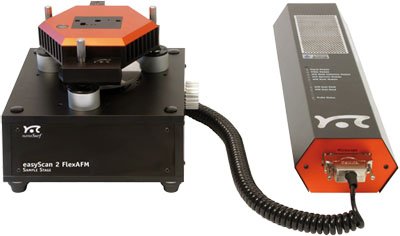
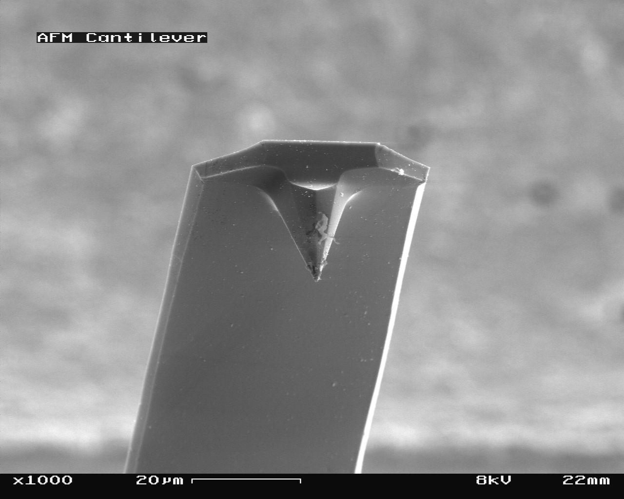
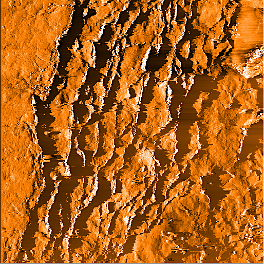
The Flex-AFM made by Nanosurf is a very reliable tool for topographical and metrological imaging of samples in both air and liquid.
It has also been used for advanced mechanical, electrical, or magnetic characterization.
Resonant Ultrasound Spectroscopy

The Modulus II device measures the elastic properties of materials by using the principle of Resonant Ultrasound Spectroscopy (RUS).
The technique employed here works because the mechanical resonances of a solid are dependent upon geometry, density, crystalline
symmetry, and elastic constants. The apparatus is a dedicated, rather than a general, analytical tool and thus it is designed
uniquely and specifically for this particular task. There is only one model available form Dynamic Resonance Systems (DRS).
No other apparatus is available for taking the needed measurements and doing the requisite analysis.
The key to obtaining accurate moduli from a RUS measurement is to ensure that the measured resonances are those of a free body.
This requires very weak transducer contact, and therefore signals are small. To extract such signals, the DRS International system
uses state-of-the-art low-noise components in a digitally synthesized/filtered heterodyne swept-sine signal analyzer. As with all
such systems, phase and amplitude information appears at an intermediate frequency or IF (977 Hz for the DRS system).
The DRS system employs a fully digital IF processing scheme with user-selectable filtering via the number of IF cycles processed
for each data point. The DRS system also allows the user to adjust a delay between points to allow the sample "ringing" to settle,
and provides user-adjustable drive amplitude and number of data points taken. To implement all these features, the hardware is
controlled by a WINDOWS software package.
Fourier Transform Infrared Spectroscopy
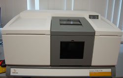
Varian 7000 FTIR Spectrometer System with MTEC Model 300 Photoacoustic Spectrometer System (NIR and MIR Regions)
(1) 125 W High intensity water cooled ceramic IR source (range 9,600-50 cm-1), PERMATRAC 2™ A 60 degree Michelson air
bearing interferometer, a design found only on the highest quality research grade spectrometers. The PERMATRAC 2™
interferometer is dynamically aligned by patented Piezo-stack technologies. The PERMATRAC 2™ interferometer in
combination with the 125 W water-cooled source deliver an unprecedented 160 mW of IR power to the sample position.
(2) 0.10 cm-1 resolution at 4,000 cm-1.
(3) Step scan capability - provides scan speeds from 800 Hz to 1 step every 250 seconds. In the amplitude modulation
mode the FTS 7000 can be used with source (e.g. chopper) or sample modulation with an external lock-in amplifier.
Phase modulation is also available, at frequencies up to 1000 Hz. Phase modulation measurements are performed in
conjunction with DSP. Step scan also includes operation in time resolved spectroscopy mode "TRS",
with 5 microsecond time resolution and event trigger.
(4) Digital Signal Processing (DSP3) for modulation experiments. Provides three modes of operation; DSP1, DSP2 and DSP3.
DSP1 demodulates the sample response in a step-scan photoacoustic measurement with phase modulation. It is a replacement
for the Varian demodulator board or a lock-in amplifier for PAS applications, providing the sample in-phase and
in-quadrature response to the phase modulation of the spectrometer.
Scanning Electron Microscope
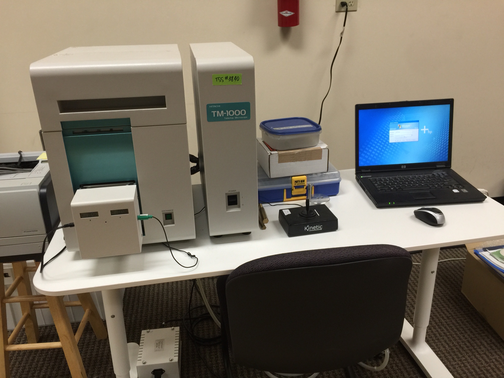
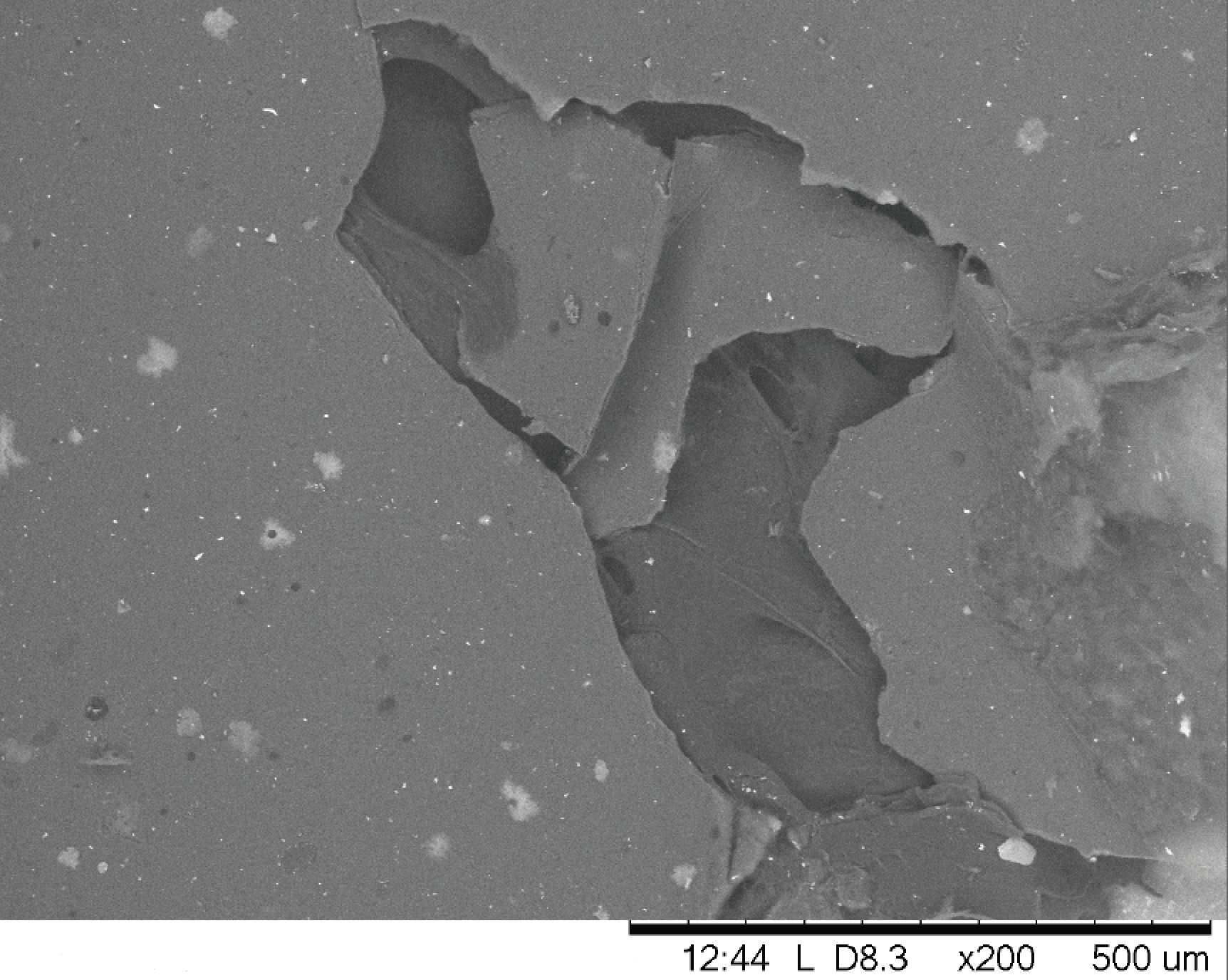
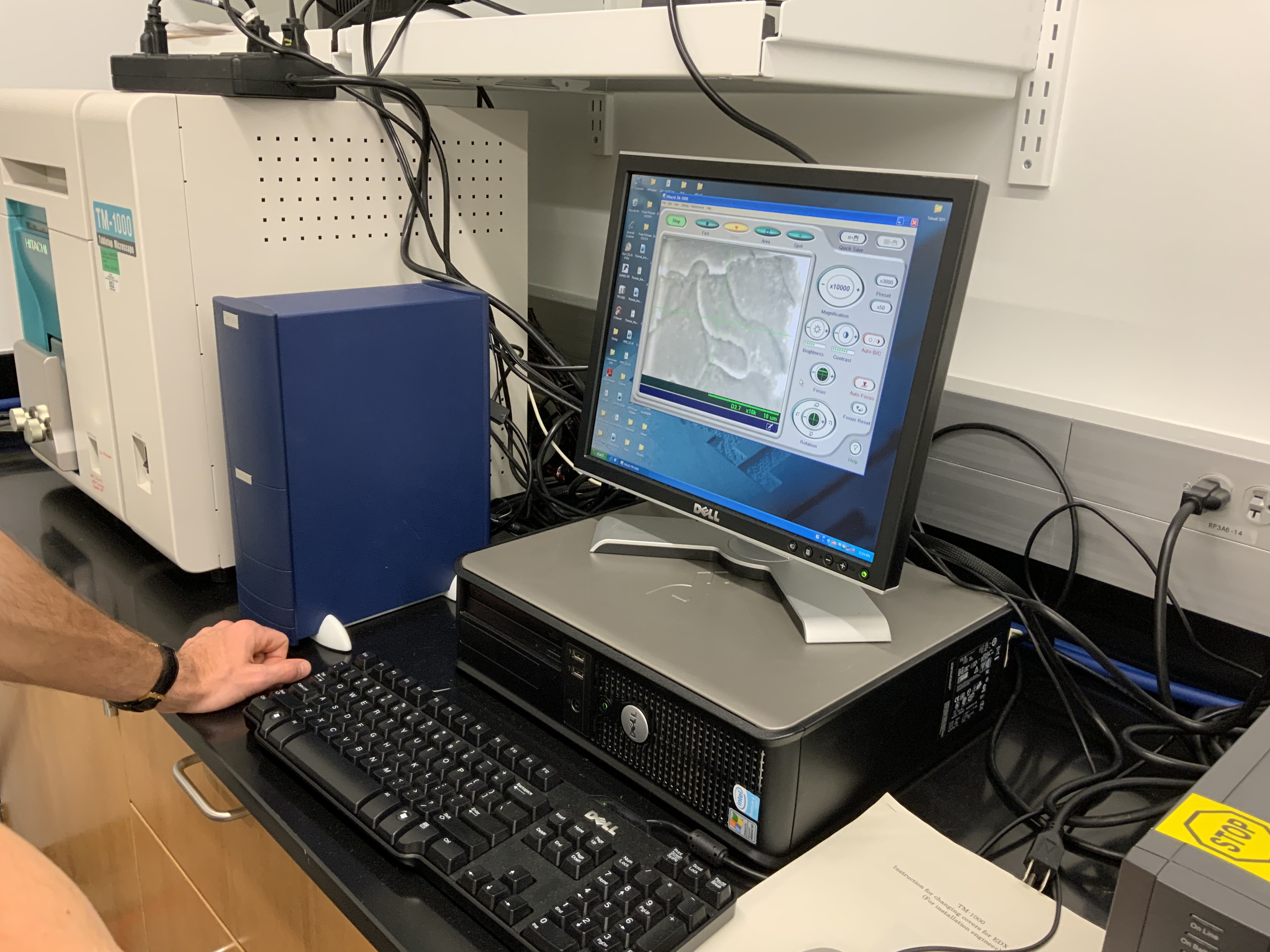
We have a Hitachi TM-1000 scanning electron microscope for faculty and student research.
Specifications of the SEM include:
Magnification: 20~10,000× (digital zoom: 2, 4×)
Accelerating voltage: 15kV
Observation mode: Standard mode/charge-up reduction mode
Specimen traverse: X:15 mm, Y:18 mm
Maximum sample size: 70mm in diameter
Maximum sample thickness: 20mm
Electron gun: Pre-centered cartridge filament.
X-ray Diffraction
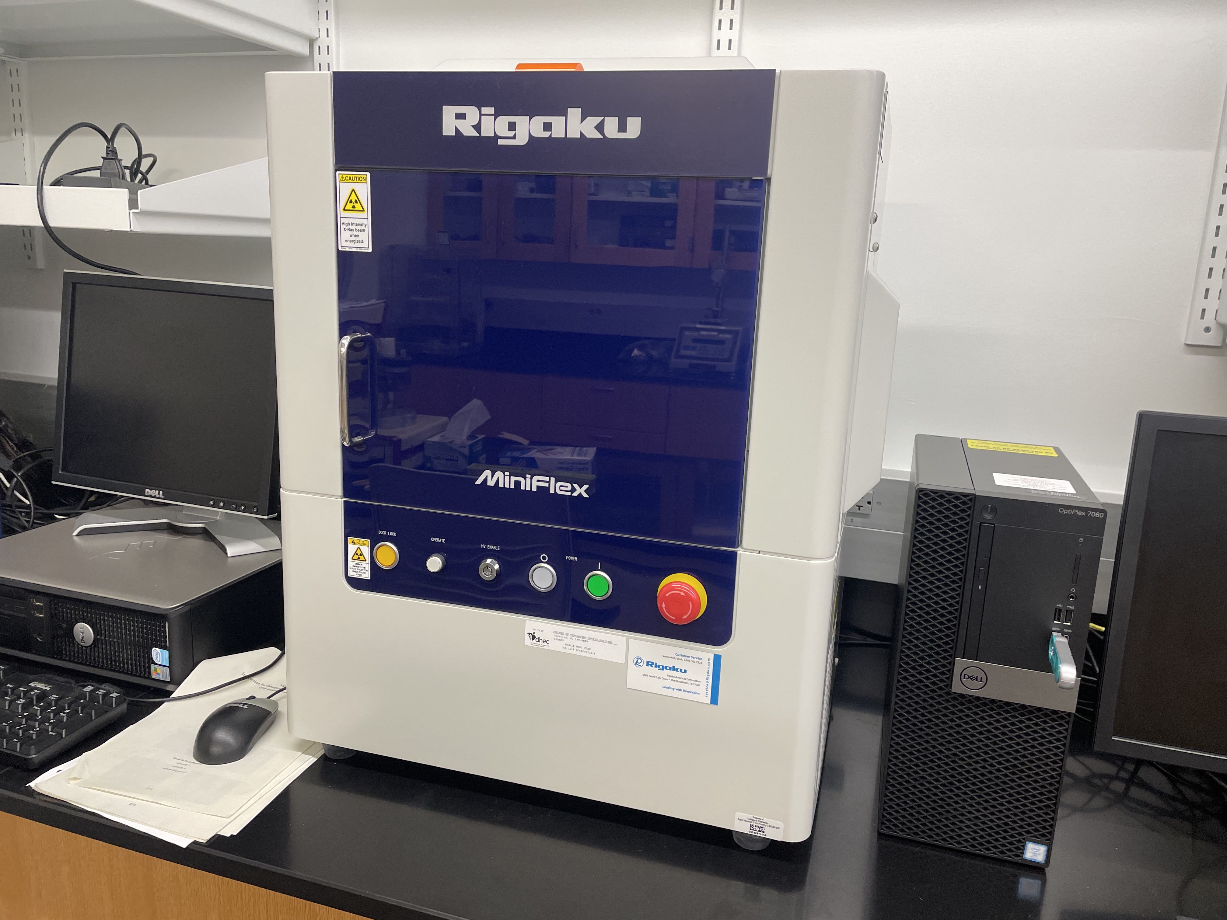
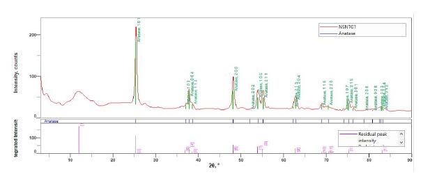
The MiniFlex 6G X-ray benchtop diffractometer is the fastest and most powerful benchtop x-ray diffraction system available in the market. It is very
flexible and is equipped with a D/teX Ultra advanced detector, slits, monochromater, and automatic sample changer. The Rugaku x-ray system was used to
characterize different doped samples of TiO2.
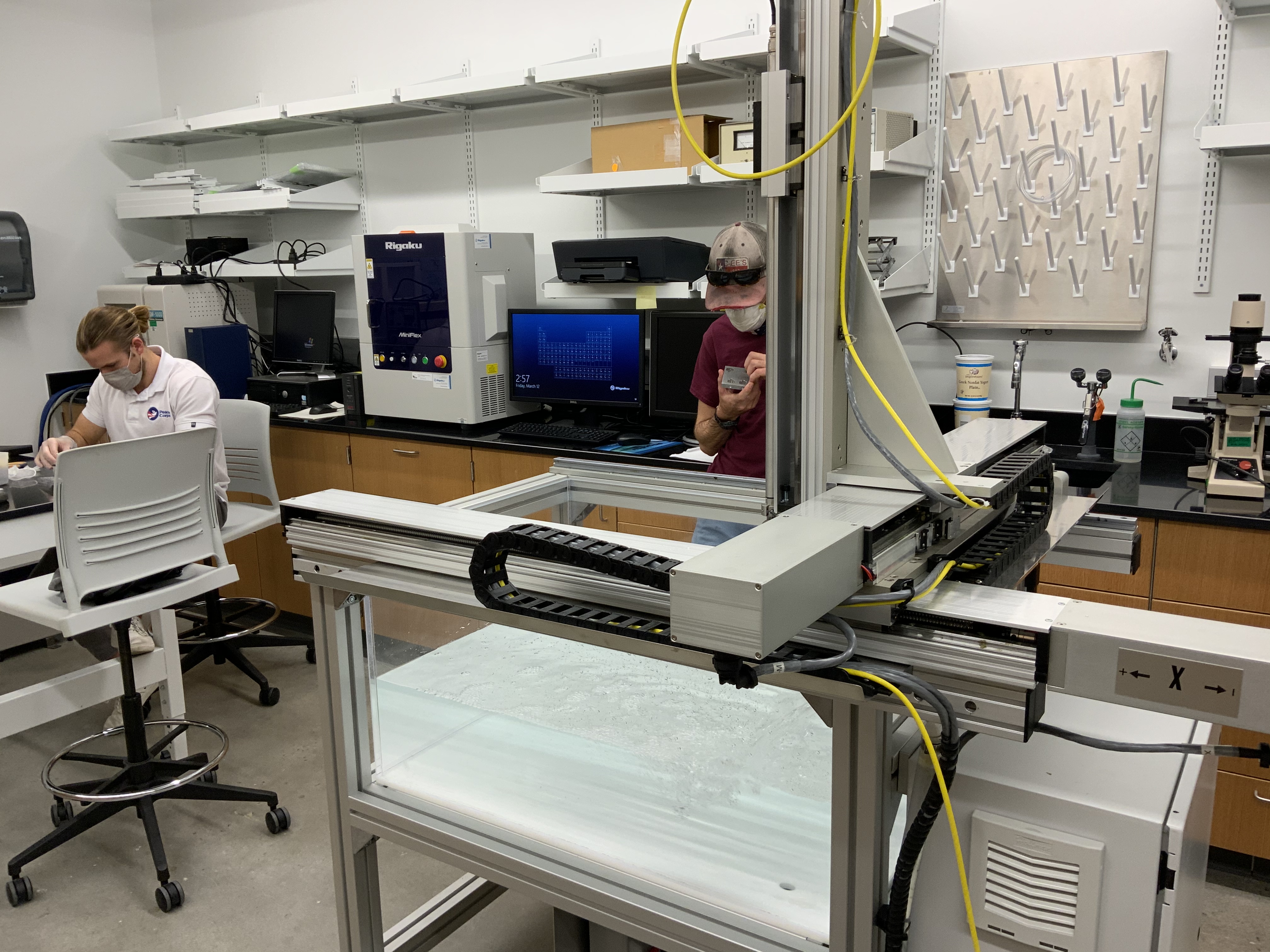
Immersion Ultrasound Scanner
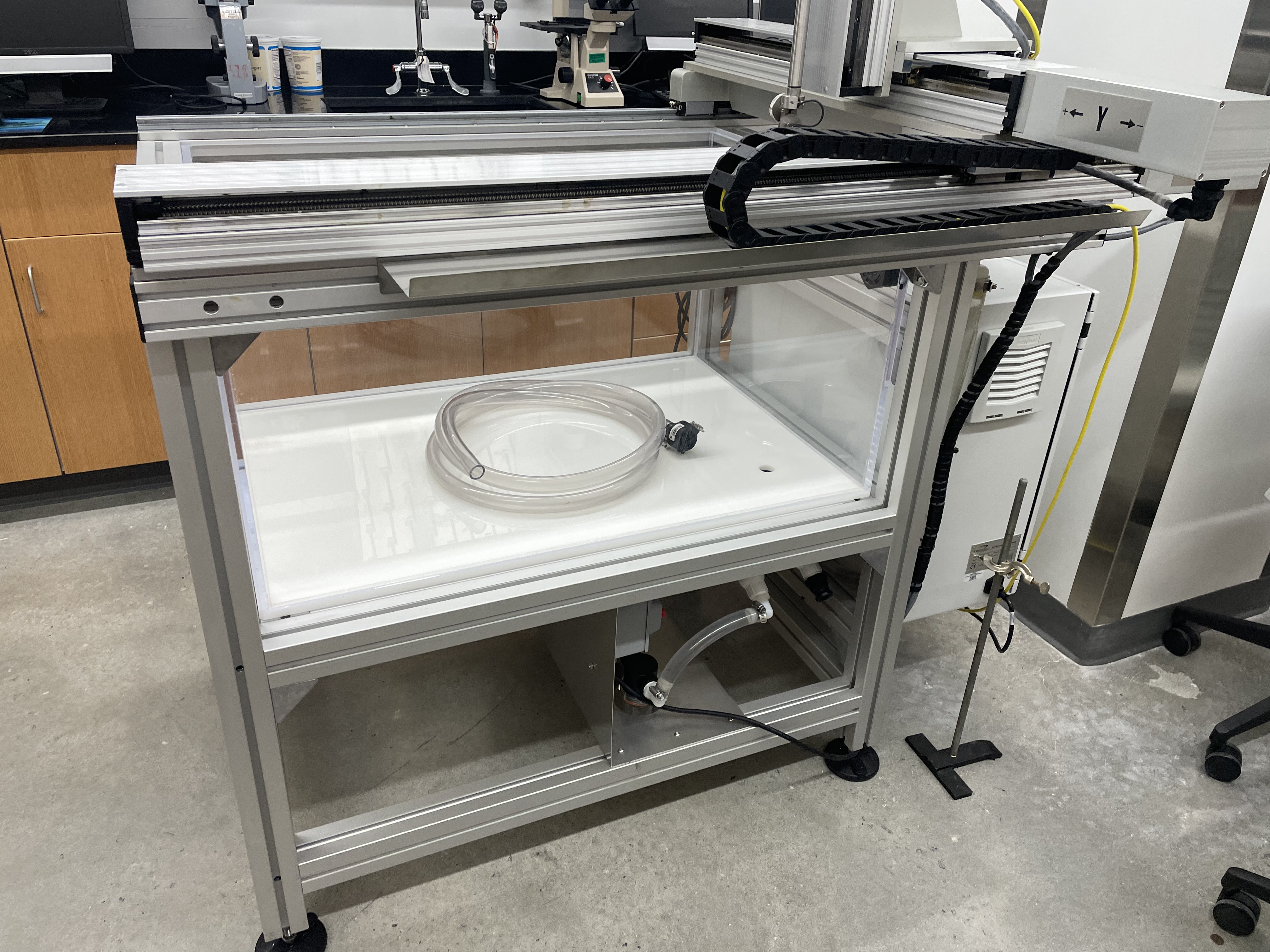
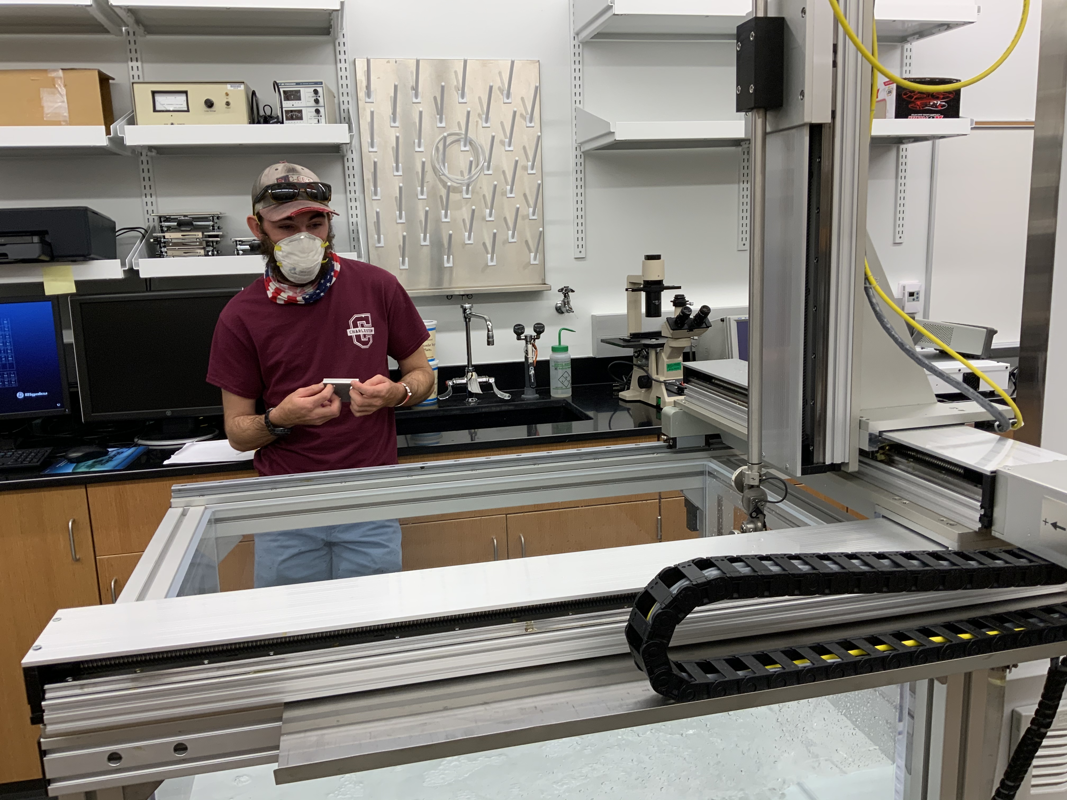
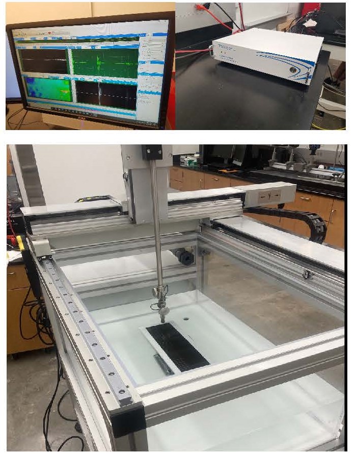
The TS-1000 immersion scanner system is a versatile computer controlled ultrasonic system used for non-destructive testing (NDT)
of materials. The immersion scanner system is designed to be rugged, highly accurate, and repeatable. It consists of aluminum
structure, acrylic tank, UTPR-50 Pulser receiver, TecView UT data acquisition/analysis software, transducers, and a 12 bit
125 MHz A/D card. It also consists of 3 axes immersion scanner - two motorized axes: X, Y and one manual Z (see Figure 1 below).
TecView UT is a Windows based software specifically designed for Ultrasonic inspections and C-scan imaging. The software is user
friendly and helps manage the entire NDT procedure, from scanner motion control to data acquisition and analysis.
It is an ideal system for hands-on training of undergraduates in NDT applications.
Laser Shearography
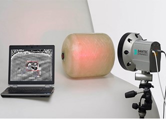
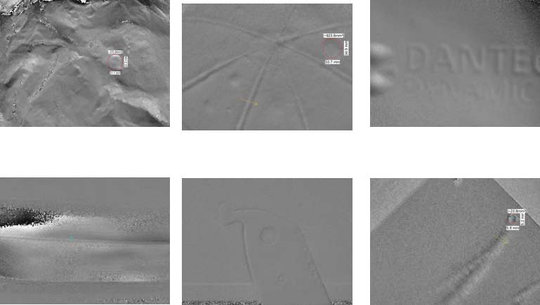
Laser Shearography is used for noncontact testing on materials like composites, plastics and in some cases metallic materials.
A 620-690 nm laser shearograph from DANTEC Dynamics was used to look for discontinuities and deformities in different samples.
Materials used in this experiment were composite, plastic, cardboard and metallic samples. With the materials we used, we compared
a neutral state to an excited state using a heat excitation method. This method heats the particles creating an excited state,
from there we can see subsurface deformities such as cracks, wrinkles, holes, etc. Using this technique, we were able to image
elevation changes and discontinuities in some of these materials and test its structural integrity. The image displayed by the system
shows the size, depth, and type of discontinuity within the material.
Schlieren Photography
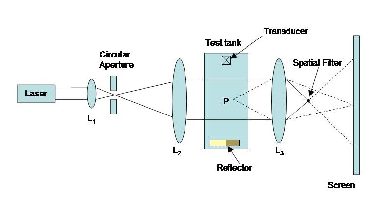
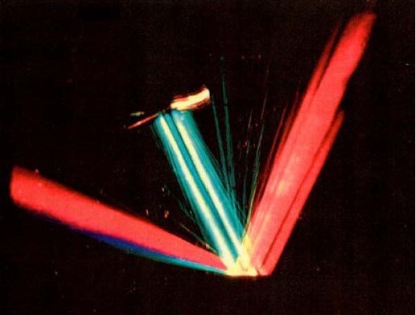
With the help of undergraduate student, a new highly sensitive monochromatic and color schlieren system was built and is available in my research lab.
The schlieren and shadowgraph are highly sensitive photographic measurement techniques used to image variations in the density and/or temperature of a medium.
I have used the schlieren technique to image bounded ultrasonic beam (analogues to a laser beam) reflected by or transmitted through a material immersed in liquid.
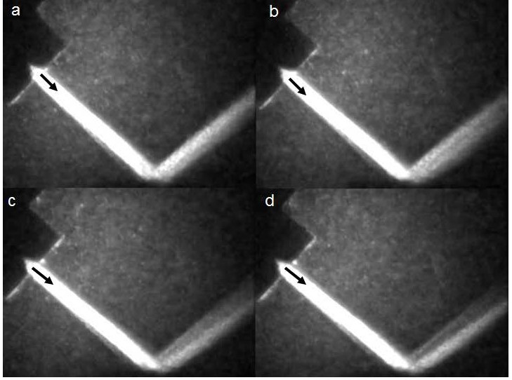
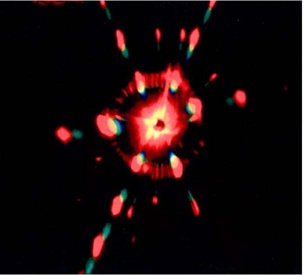
For example, a diffraction pattern is observed if a unidirectional carbon fiber reinforced epoxy is placed in front of a bounded ultrasound beam. The impact
response, fatigue damage, and stiffness of a composite all depend upon the fiber direction. Therefore, it is important to know the fiber direction during
production and maintenance processes. The direction of the fibers, the density of the fibers, and any type of imperfection in the fibers can be determined from
the diffraction patterns. This is a good example of the application of schlieren photography in nondestructive testing (NDT). In addition, the schlieren
photographic technique can be used to image an incident ultrasonic bounded beam reflected by a periodically corrugated brass surface and other alloys and the
properties of surface waves propagating on the surfaces of these metals, alloys, and composites. The schileren system can also be modified to be used as a Bragg
diffraction system. Bragg diffraction of x-rays occurs when the rays interact with a crystalline lattice at the appropriate angle. Bragg Diffraction of visible
light occurs when the light interacts at the Bragg angle with an ultrasonic field of the appropriate frequency. (The spacing between acoustic condensations and
rarefactions acts like the planes in an atomic lattice.) If a beam of light is Bragg diffracted by an ultrasonic beam that previously has passed through an object,
an image of the structure of the object is made visible in the diffraction field of the optical beam since there is a one-to-one mapping of the ultrasonic field
onto the diffraction order. In many acoustic Bragg imaging applications, the sound field must pass through the object which is to be imaged.
The schlieren photographic system is a simple optical system that can be setup with the help of undergraduate students and can be used for various
undergraduate research projects.
updated: 18 May 2022